*Easy so I thought. I figured, I have the box, this should be easy!! I have no idea why I thought this. It was not easy at all. However maybe my process or choice of parts may make your project easier. Enjoy
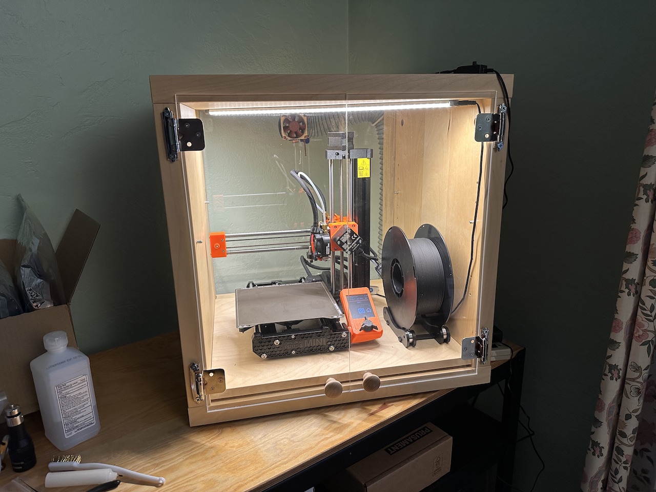
I’ll start with the final product. This is the end result and it works quite well and is very noise dampening. I do not know which IKEA thing this is, if it’s a mini bookcase or a stand. I got it a long time ago. The box came with a shelf, so I added rubber feet to the shelf and put the printer on top of it. I was trying to make it quiet and uncouple it from the box and table below. You can see the shelf and the gap below it. The knobs are from Home Depot and make of wood. In the back corner I drilled a hole and added an eyelet screw. I tied a rope from the eyelet around the hose to hold it up as strain relief for the fan connector.
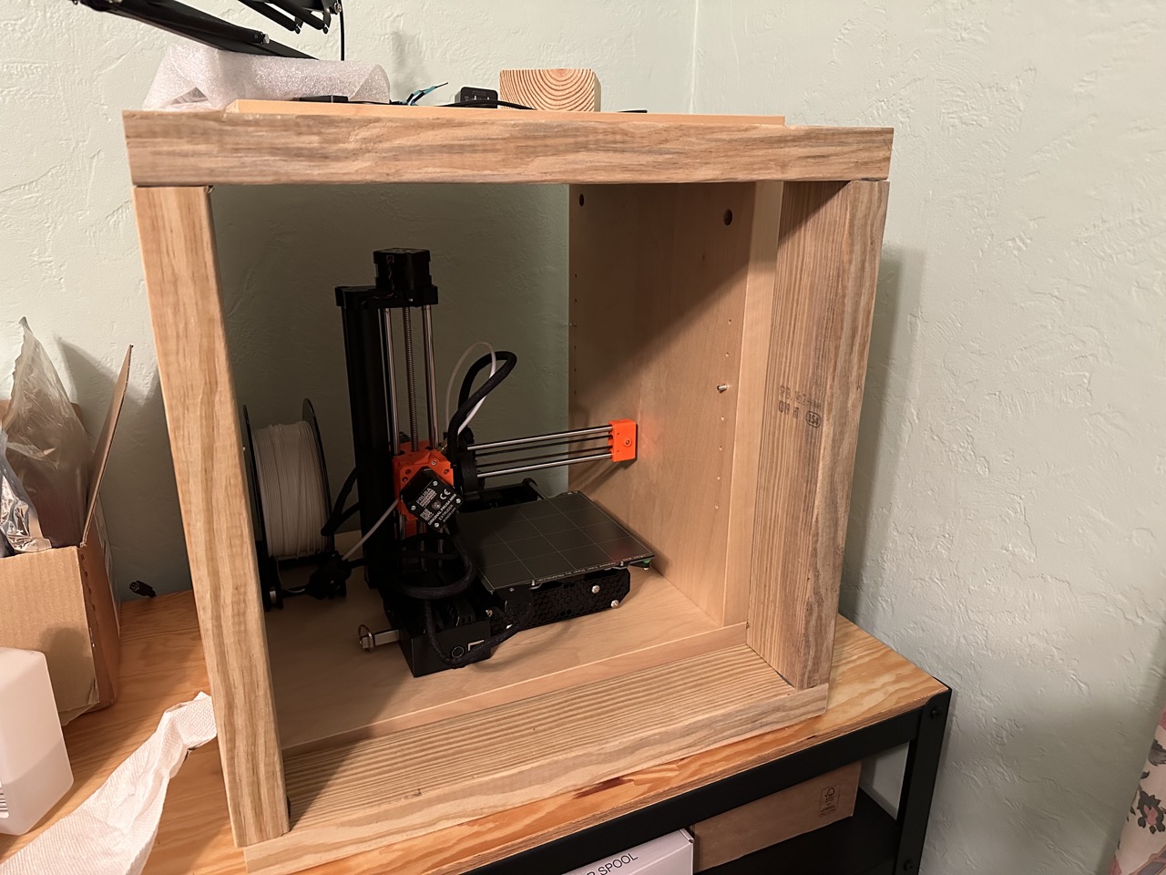
Back side photo. I realized rather quickly that my IKEA box was not deep enough since the cable for the bed temperature sensor would hit the back of the box. I had to extend it a bit. The simplest thing was to cut up a 2×4 and glue it together and glue it in place. I was way too lazy to drill and screw all that together. The glue I used was Liquid nails Fuze*It. It’s super strong and worked well. It just so happened that the wood was the same thickness as the walls of the box.
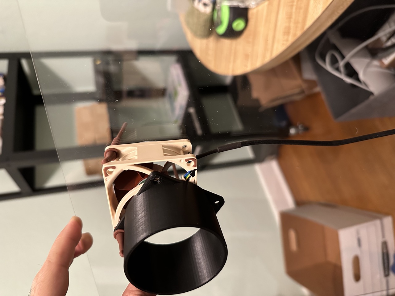
I used a Noctua NF-A6x25 PWM, Premium Quiet Fan, 4-Pin with a Noctua NA-FC1, 4-Pin PWM Fan Controller (Black) speed controller, and Coolerguys 12V Fan Power Supply The black part is a 3D printed adapter I designed to fit onto the fan. The hose I used was 2-1/2 inch Diameter by 10 foot Long PVC Dust it came with the clamps. I used these rubber grommet things that came with a different Noctura fan to hold the fan and hose adapter to the back. Screws would have been better because the rubber grommets flexed a bit and could create an air gap.
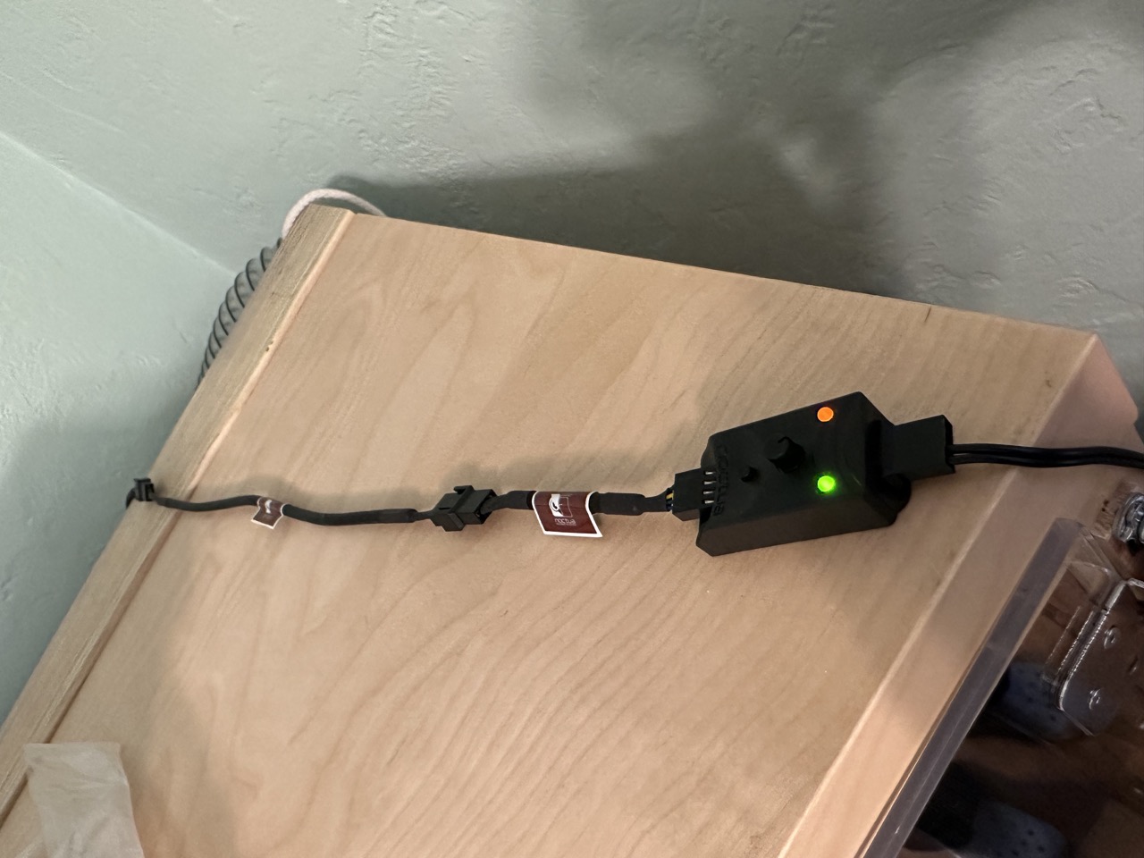
Below is the fan speed controller. I used 4 pin parts for everything so it was an easy fit. I can just turn the dial and adjust the fan speed. You can see the rope tied to the eyelet that holds the hose.
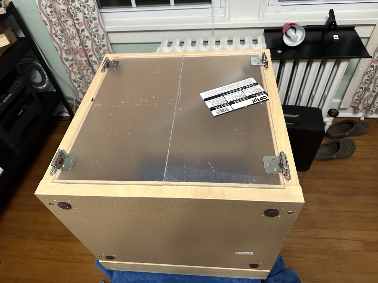
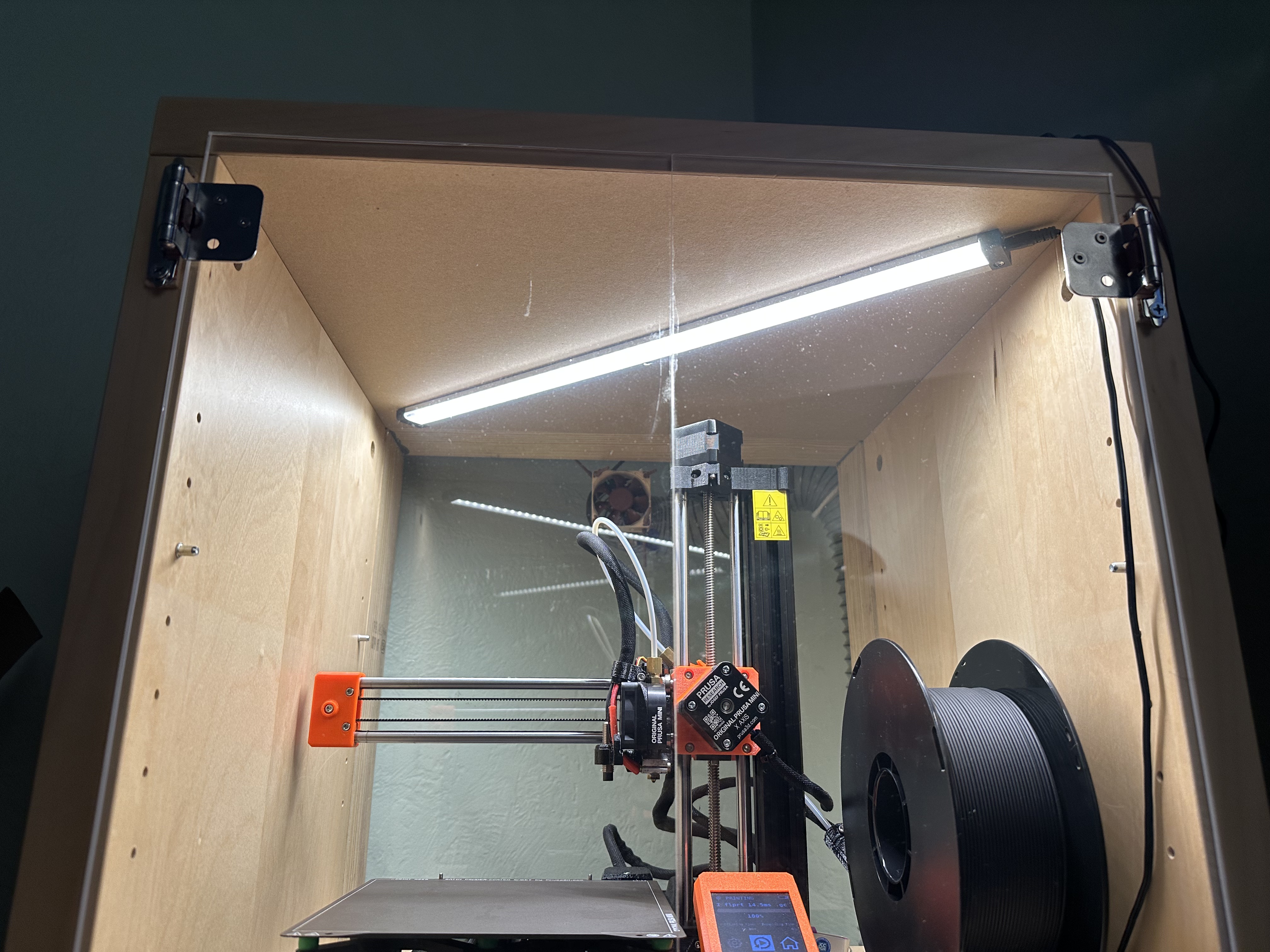
This is the box with the 1/4″ plexiglass cut to size. I used a plexiglass scoring tool to cut it down to size. It was a bit of a pain. I wanted precise cuts so I used the factory cut side for where the doors meet since it was a better edge. The hinges are from Home Depot. They are inexpensive and they hold themselves closed with a built in spring mechanism . To prevent air gaps, I mounted the hinges in front of the doors so they would sit flush against the cabinet face. It’s not how they are designed to be used, so I had to add spaces to make thing work. I used a steel ruler and clamps to score the plex and clamped it to a work bench. I scored and snapped the plexiglass.
Here you can see looking from bottom the hinge sitting crooked. I used a paint stick cut down to size as a shim, but it was not enough. I had to add few screws as spacers.
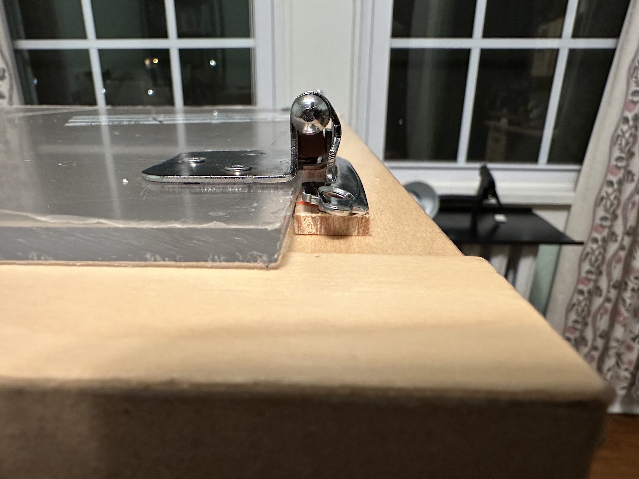
Here you can see the hing with the wood paint stir stick and the washers I needed to add to get the door spacing correct. I only used 2 screws to hold the doors on because they didn’t need more and I’m lazy.
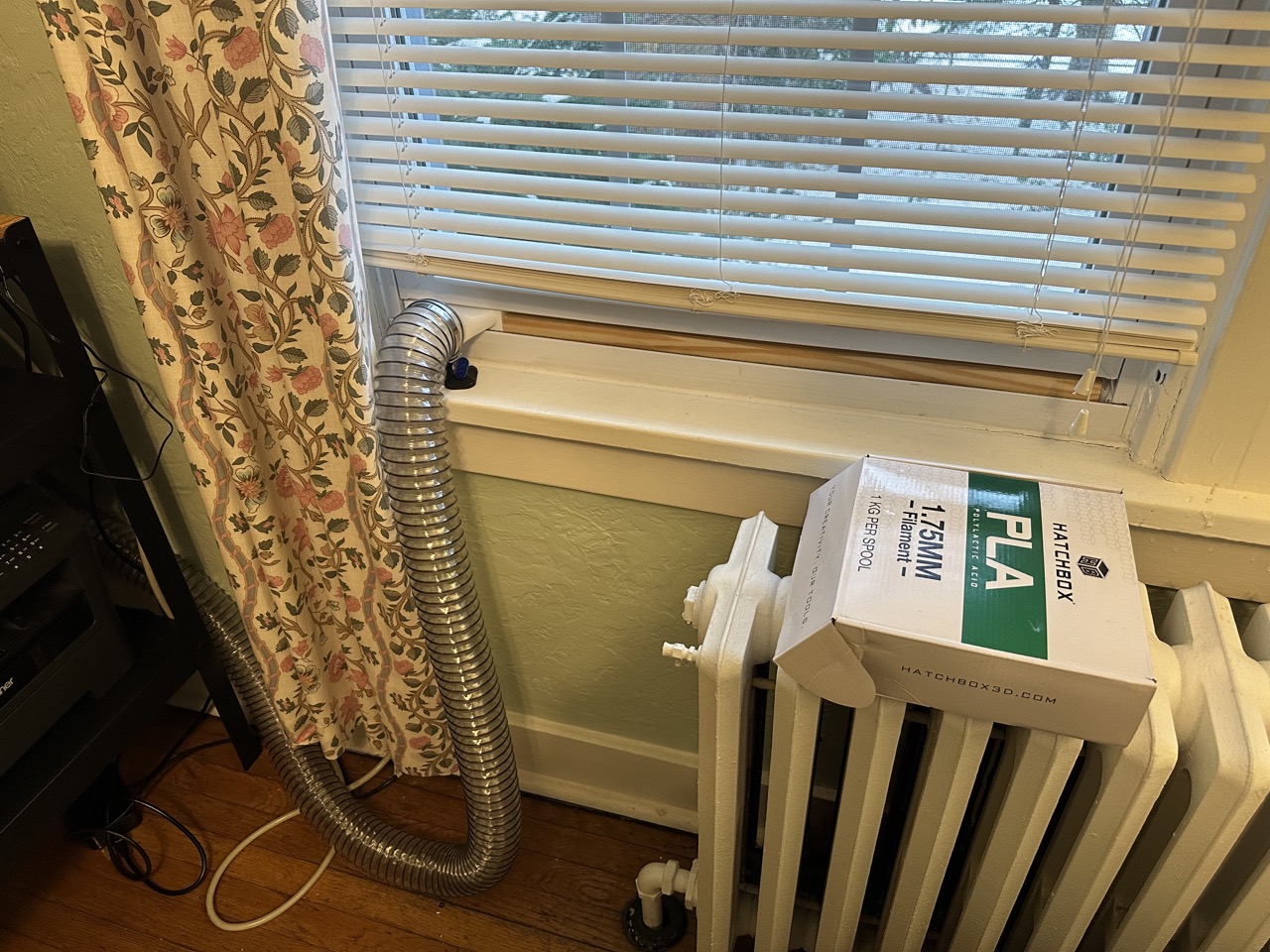
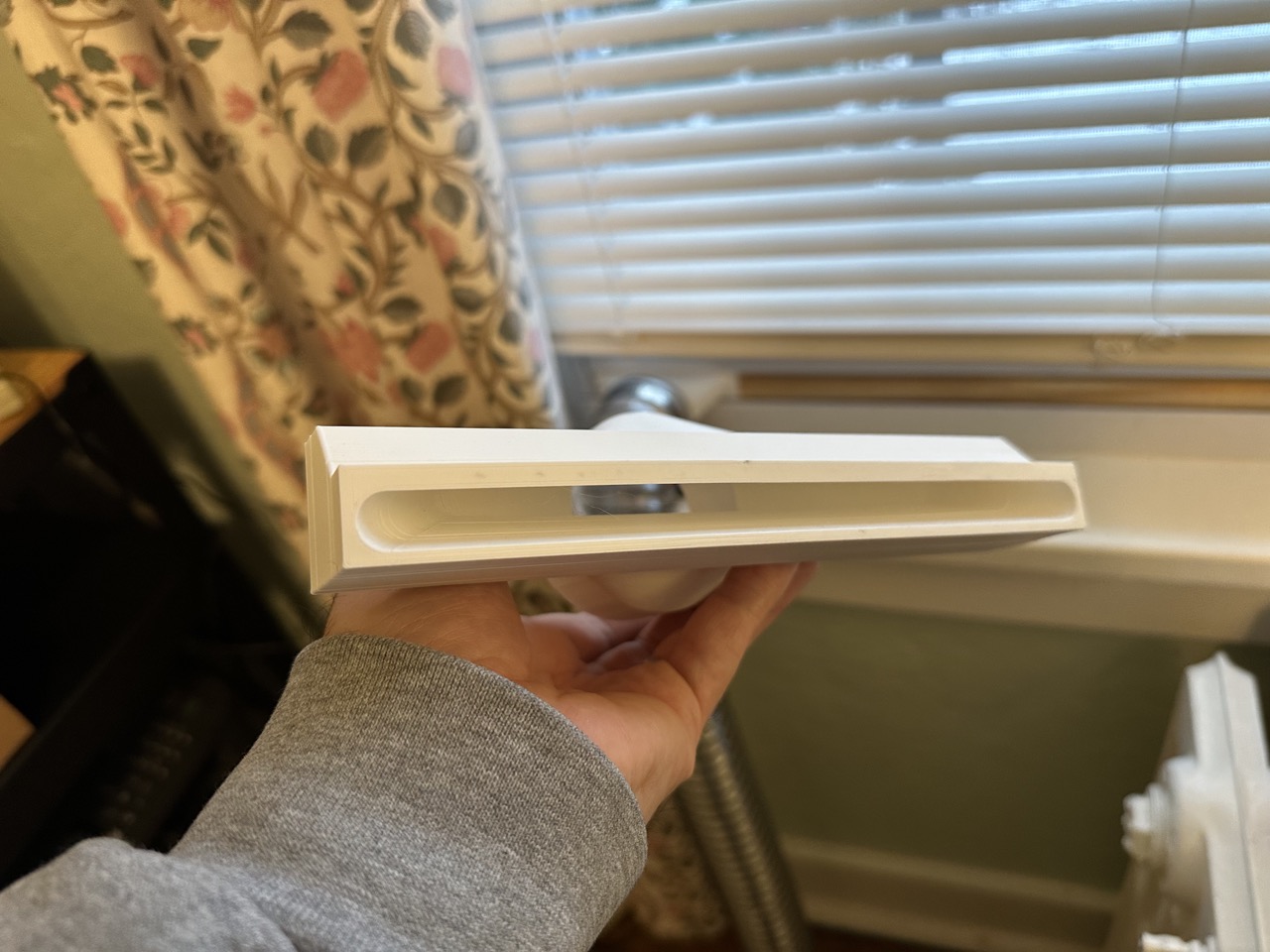
This is how the hose vents outdoors. I designed a bracket to take it from a round shape to an oval so the window would only have to open a small amount. I cut some wood and tapered it to fill the remainder of the gap using a bandsaw. The windowsill has an angle on the outside so I had to cut the wood and design the part to fit without gaps.
This is the part I originally made to adapt the hose to the window. It’s wide so that the volume is the same going from a circular opening to an oval. This part didn’t quite fit, so I designed the other one you see with the hose connected. I don’t need to move a lot of air. I just need less air pressure in the enclosure than in the room to vent. The hose is 2.5″ diameter more than enough to move air.
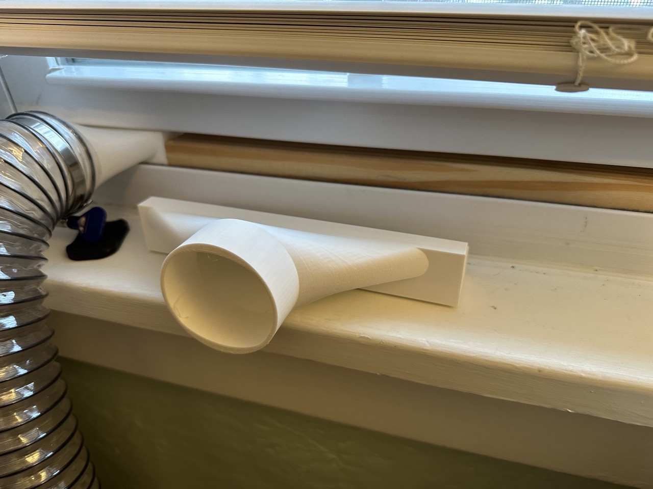
Here is what the front of the adapter looks like. It fits the bottom of the window and when the window closes it creates the tight seal.
I use an LED motion activated light since I already had one. Lucky when the printer moves up it does not trigger the light to turn off or on.
Here’s a quick video tour
Wrap up
Airflow
The box has a fairly tight seal, but there are some gaps in the front corners by the doors and a small one in the back. There is a hole drilled in the back plastic (center bottom) for the power cords. When I print I leave one door slightly ajar or sometimes just close the doors. The doors meet and sit so tight that I can just close one door and leave the other door resting on the edge of the other door. It leaves about a .25″ gap. Either way with the doors open or closed, it draws enough air that I never smell the melting plastic.
Plexiglass thickness and experience cutting and drilling
Drilling and cutting was a bit of a pain. Drilling the large hole for the fan was a bit scary because the holesaw bit would catch and yank the drill. Drilling the holes was also tedious because plexiglass can fracture. I started with small drill bits and worked progressively larger. Scoring and snapping the plexiglass was kinda fun. The thickness for the doors was 1/4″ thick and the back was thinner, but I don’t remember the thickness.
Cost
I also thought this would be cheaper since I had the box, and I was wrong. Here’s the price break down.
$33.78 plexiglass for front
$33.96 plexiglass for back
$15.00 fan
$24.00 fan speed controller
$ 8.00 power adapter
$24.00 hose
$2.20 door knobs
$1.34 washers
$1.98 wood for window
$7.78 acrylic cutting tool
$5.47 foam tape
$7.96 hinge
$49.97 hole saw cutting toolset
$215.44 Total